[ Home ] [ Accessory Drive ] [ Bonnet Hinges ] [ Cooling ] [ Calculators ] [ Conversion Parts ] [ Drivetrain ] [ Electric Windows ] [ Engine ] [ Engine Install ] [ Engine Mounts ] [ Fuel Tank ] [ Interior ] [ Movies ] [ Oil Pans ] [ Power Steering ] [ Seat Rails ] [ Specifications and NCOP ] [ Starter Motors ] [ Suspension ] [ Wipers ] [ Links ]
K-Frame
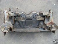
The LH/LX/UC 4 cyl Starfire, 6 cyl and V8 k-frames are all
basically the same. The only significantly different k-frame is the one used
with the Opel 4 cyl which has a different engine mount and can not be used with
the 6 cyl and V8 engine mounts.
Early LH k-frames do not have the sway bar mount
holes however these can be easily added.
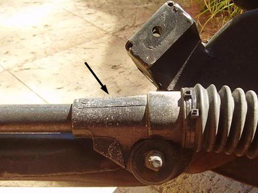
A cover for the steering rag joint coupler was added during the LX model.
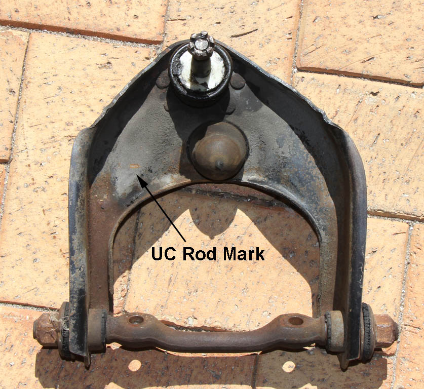
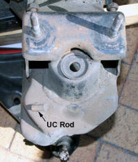
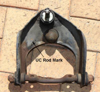
The UC k-frame has a
small bit of steel rod welded to the top of the outer ends of the k-frame just
under the UCA. The purpose of this rod is unclear, it appears to be an additional
bump
stop to prevent the control arm binding on the k-frame when the suspension is at
full extension as the higher UCA bolt position reduces the effectiveness of the
rubber bump stop. The UC k-frame also has a reinforcing washer spot welded to
the upper shock mount.
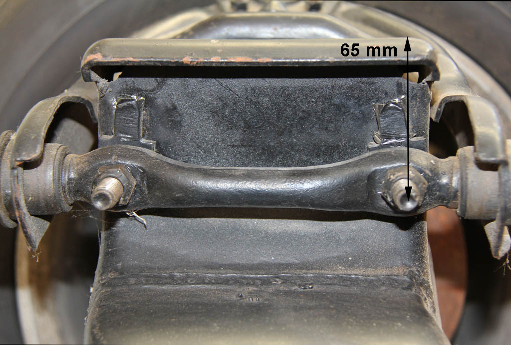
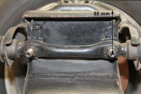
The main method of
identifying the k-frame is via the position of the Upper
Control Arm (UCA) mount bolts.
The bolt
holes are 7/16" the bolt has splines which makes it a press fit into the hole.
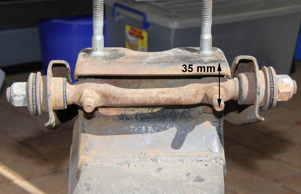
LH/LX non RTS 50mm
LX RTS 65mm
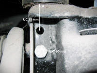
UC 35mm
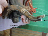
A9X 60 mm and the UC 35 mm mount position. The lower holes we used on the A9X
due to the
HZ one tonner stub axles
used on the A9X.
The
axle on the A9X stub axle is mounted approximately 20 mm higher up the stub axle
than it is on the standard Torana stub axle which lowers the ride height by
approximately 20 mm. The A9X was also fitted with the taller DR70H14 tyres (Dia
636 mm) vs. the standard
CR70H13 (Dia 575 mm). The DR70H14 is around 61 mm taller than the CR70H13 which would
make increase the ride height by around 30.5 mm. I have not been able to get
accurate measurements of the diameter of the factory tyres so the figures ar e a bit rubbery, however basically the taller A9X tyre cancels out the effect
of the lower A9X stub axle.
The top of taller
A9X tyre would also travel 20 mm + 30.5 mm further into the guard so a compression bump stop spacer was welded to the
A9X k-frame to reduce the amount of compression suspension travel. The A9X diff also has
compression bump stops that are around 1" taller than the standard Torana diff.
If you were to fit A9X
stub axles to your Torana and not change rim/tyres or springs then the car will
be around 20 mm lower than it was with standard Torana stub axles.
|
|
|
|
UC K-frame rod and spot welded reinforced upper shock mount
|
|
|
|
UC Rod Mark
|
|
|
|
LX RTS 65 mm
|
|

|
|
UC 35 mm
|
|
|
|
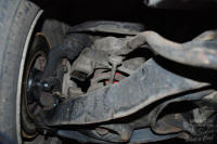
A9X has the UC 35 mm and the A9X 60 mm bolt holes
Picture by Dangerous
Note the A9X k-frame has the reinforced upper shock mount. |
|
|
|
|
|
A9X Compression bump stop spacer
|
|
|
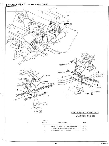
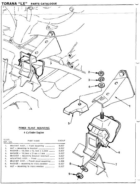
The bracket in view A is welded to the k-frame for the
Starfire 4 cyl, 6 cyl and V8.
|
|

|
|
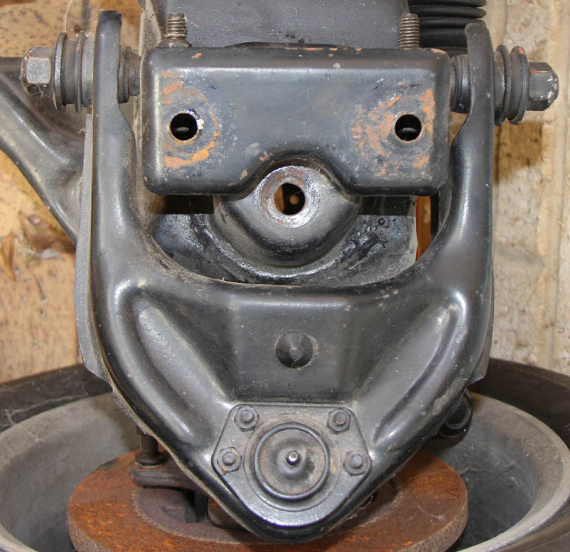
Starfire 4cyl, Holden 6cyl and Holden V8 engine mount
|
|

|
|
Bracket part #7 in this picture is welded to the k-frame to mount the Opel 4 cyl motor.
|
|
|
Upper Control Arm (UCA)
The LH and LX use the same UCA although the LH arm may have been made from
thicker steel. The
ball joint is offset 0.5" (12.7 mm) on the
UC version of the
UCA , this gives more positive caster than the
LH and LX UCA's. which are symmetrical.
|
|

|
|
LX Upper Control Arm (UCA)
The left and right LX arms are the same part number. |
|

|
|
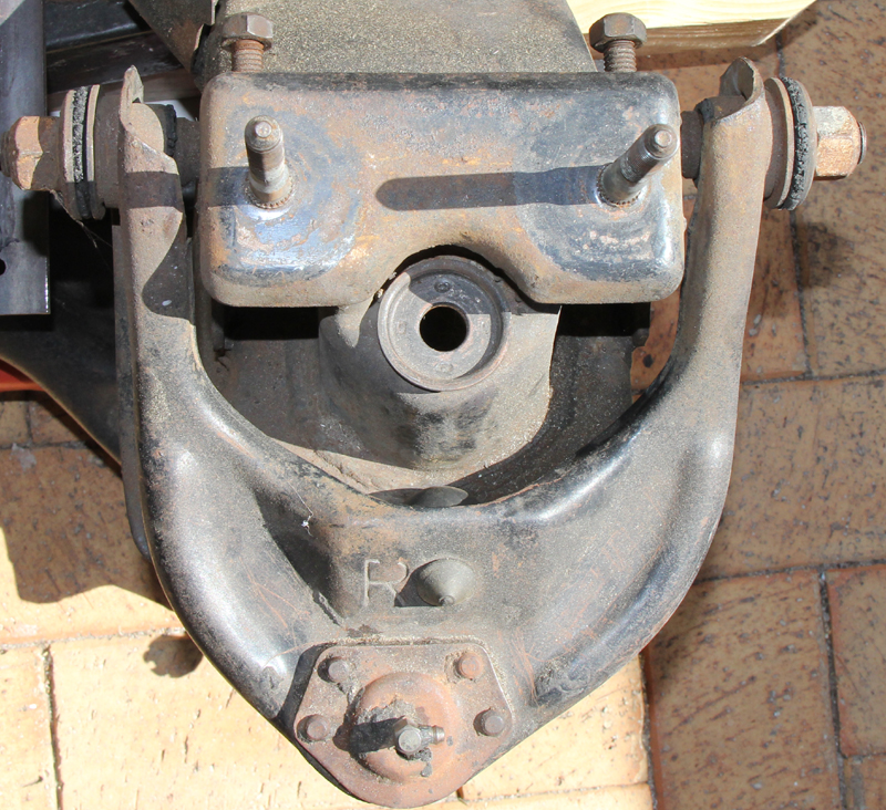
UC Upper Control Arm (UCA
There is a left and a right UC UCA. Note the letter R stamped on the right UCA.
Note the upper shock hole on the UC k-frame has a washer spot welded to reinforce the mount.
|
|
|
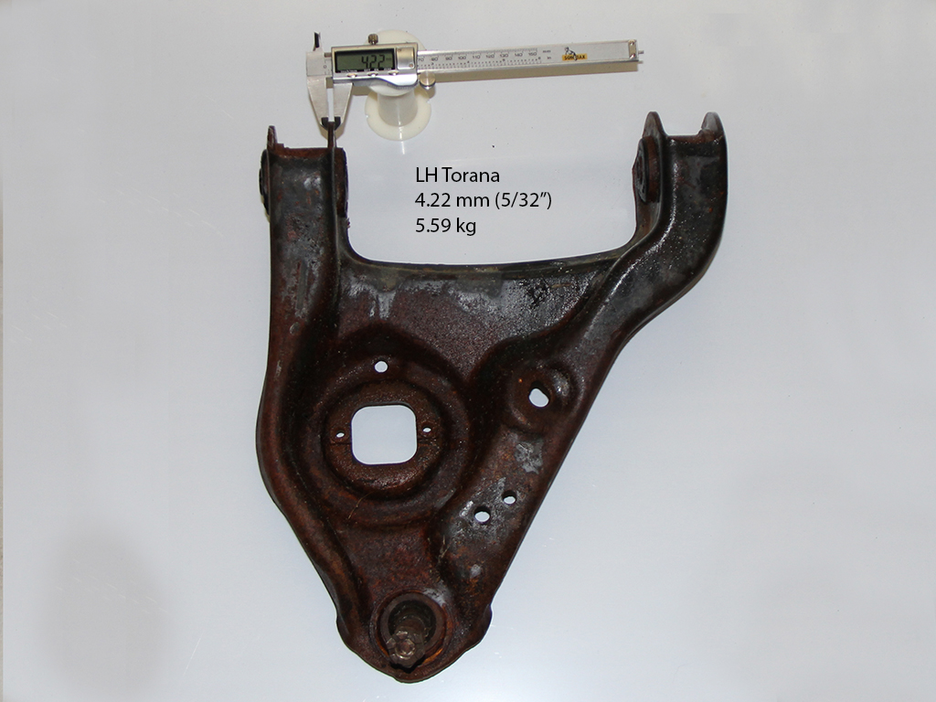
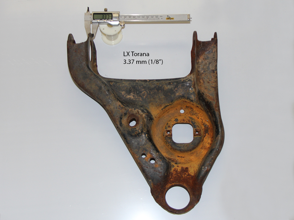
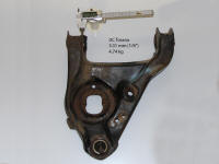
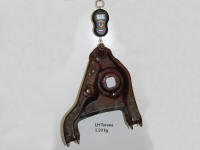
Lower Control Arm (LCA).
The geometry of the
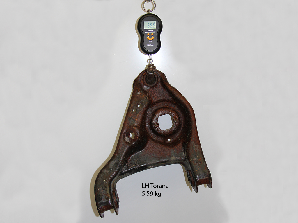
LCA is the same throughout all models. The LH and LX LCA are identical with the
exception that the LH arm 5.59 kg is made from 5/32" (4.22 mm) and the LX is made from
1/8" (3.7 mm) pressed
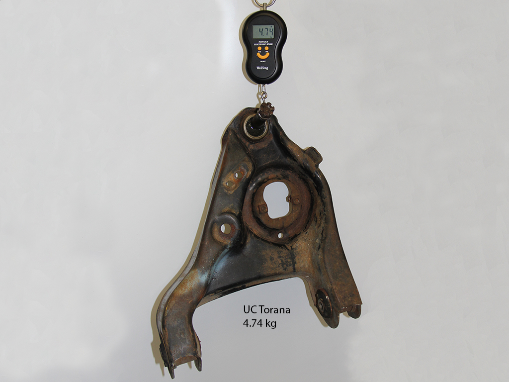
steel. The LCA on the UC 4.74 kg is also made from 1/8" (3.31 mm) pressed steel. The LH and LX
LCA do not have steering arm bump stops. The UC LCA has steering arm bump stops.
The UC LCA has a larger hole for the shock absorber to fit through. The LH and
LX LCA shock hole can be enlarged to the same size as the UC.
|
|

|
|
LH LCA 5/32"
|
|

|
|
LX LCA 1/8"
|
|
|
|
UC LCA 1/8" 4.74 kg
Enlarged shock hole and steering stop. |
|
|
|
LH LCA 5/32" 5.59 kg
|
|

|
|
UC LCA 1/8" 4.74 kg
Enlarged shock hole and steering stop. |
|
|
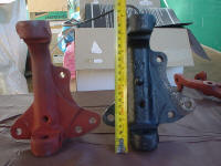
Stub Axles
The A9X uses HZ one tonner stub axles.
| Model |
Position |
Included Angle |
Part Number |
| LH/LX Drum |
Both |
9 |
7448795 |
| LH/LX Disc |
Left |
9 |
9934548 |
| LH/LX Disc |
Right |
9 |
9934547 |
|
L34 |
Left |
|
9932964 |
|
L34 |
Right |
|
9932965 |
|
A9X |
Left |
7.5 |
9943695 |
|
A9X |
Right |
7.5 |
9943696 |
| UC Disc |
Left |
9 |
92000163 |
| UC Disc |
Right |
9 |
92000164 |
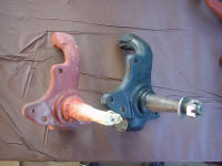
The A9X Stub Axle lowers the car 20 mm and increases negative camber by
1.5 degrees . The track
is not increased by either the stub axle or the HQ discs. The A9X track was
increased as a result of fitting different offset rims. The A9X or Harrop reproduction steering arms should be used with the
A9X
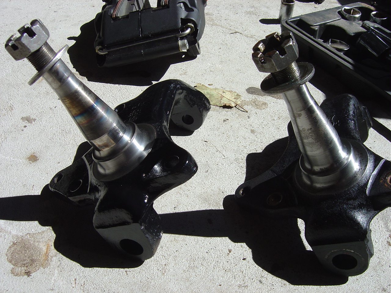
stub axle to correct the bump steer caused by the altered suspension geometry. The A9X and HZ one tonner stub axle have been heat treated
which gives them a blue tinge. There is also more steel around the lower ball
joint mount. The HZ car stub axle is identical in geometry and has a different
part number.
If you fit A9X stub axles and change the springs to retain
the same ride height as you had with the Torana stub axles then the track will
change a small amount due to the change in the angle of the lower control arm at
ride height. When the lower control arm is horizontal the track will be at its
widest. As the lower control arm moves away from horizontal the track will
reduce as the stub axle is swung through an arc.
|
|
|
|
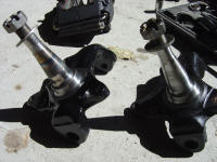
LX Left. A9X Right
Picture by Dangerous
Note the different height of the axle center. |
|
|
|
LX Left. A9X Right
Picture by Dangerous
|
|
|
|
HZ One Tonner (A9X) Left. HZ other Right
Note the heat treating and heavier casting on the HZ One Tonner.
Picture by Rorym
|
|
|
|
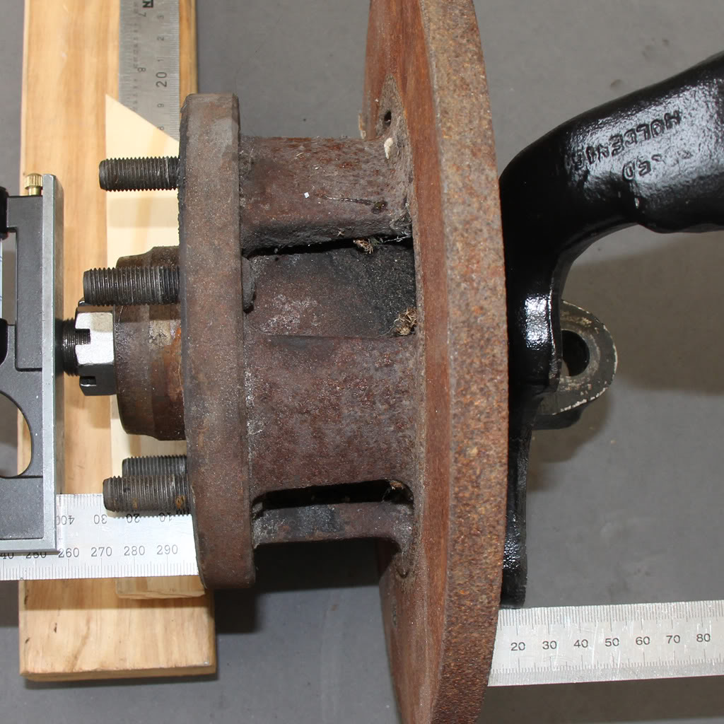
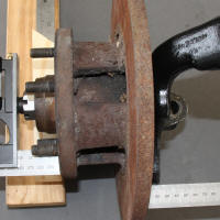
LX stub axle with LX disc
42 mm from stub axle tip to BUF
No change in track |
|
|
|
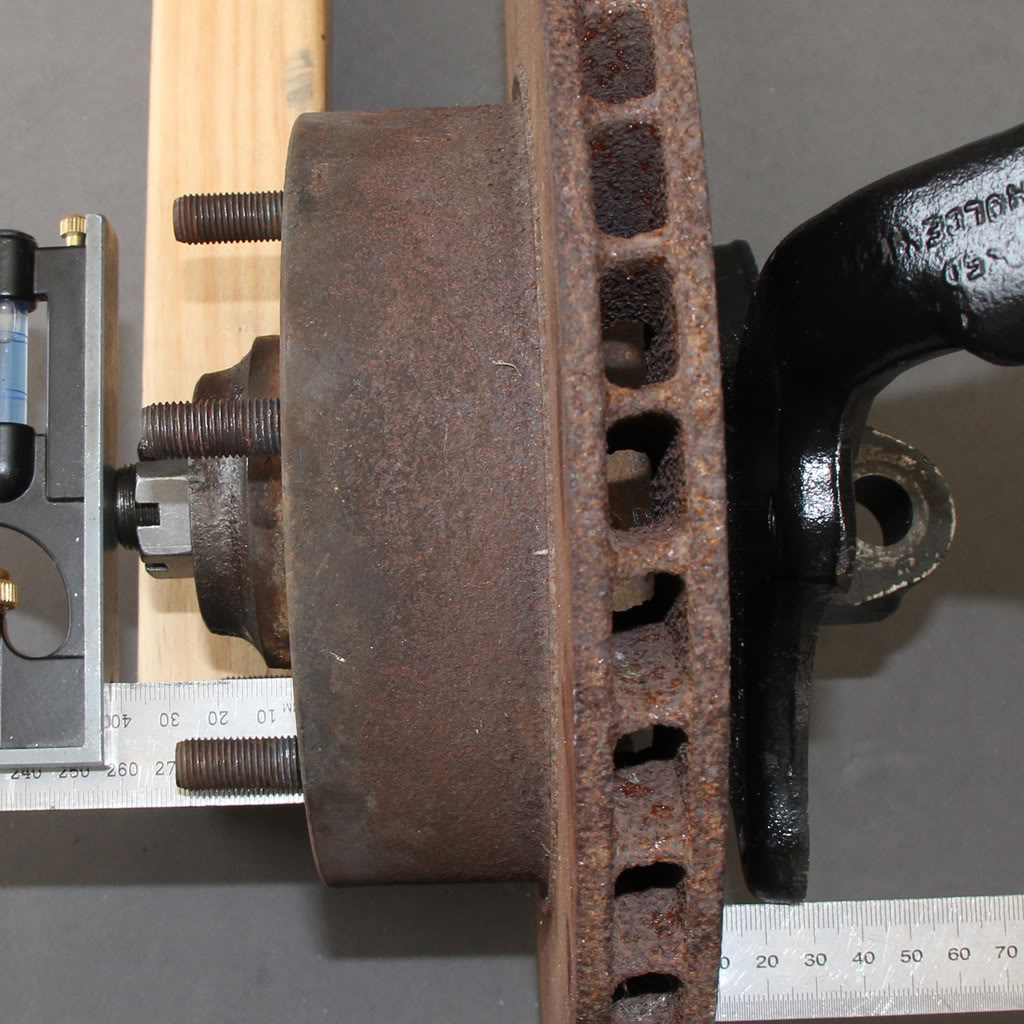
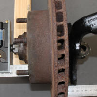
LX stub axle with HQ disc
42 mm from stub axle tip to BUF
No change in track |
|
|
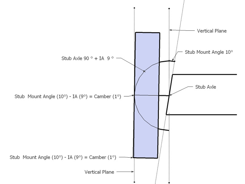
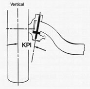
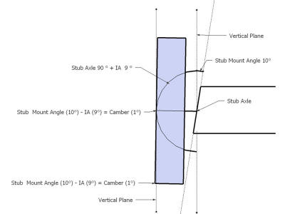
Included Angle (IA)
This is the angle that is built into the stub axle. It is
often incorrectly referred to as the King Pin Inclination (KPI).
King Pin Inclination (KPI)
KPI is the inward tilt from vertical in degrees. The KPI is
the sum of the camber angle and the included angle built into the stub axle.
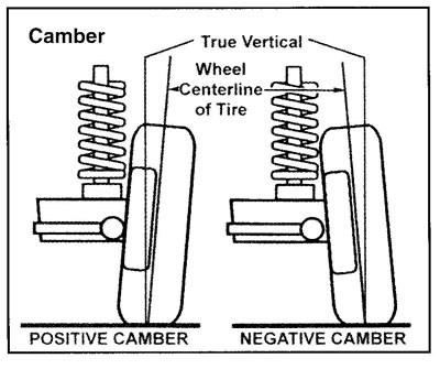
Camber Angle
Camber angle is the angle made by the wheels of a vehicle; specifically, it is
the angle between the vertical axis of the wheels used for steering and the
vertical axis of the vehicle when viewed from the front or rear. It is used in
the design of steering and suspension. If the top of the wheel is farther out
than the bottom (that is, away from the axle), it is called positive camber; if
the bottom of the wheel is farther out than the top, it is called negative
camber.
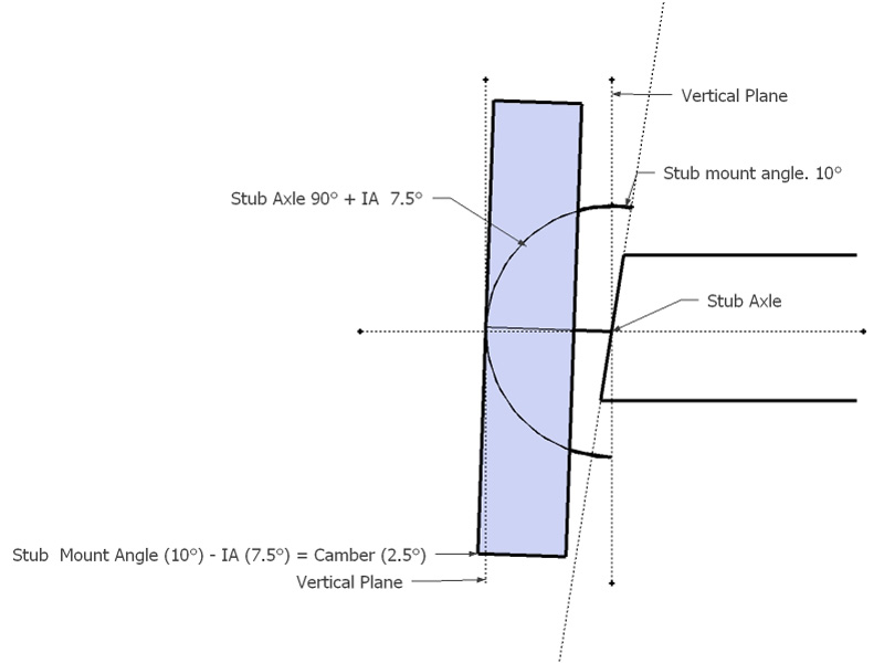
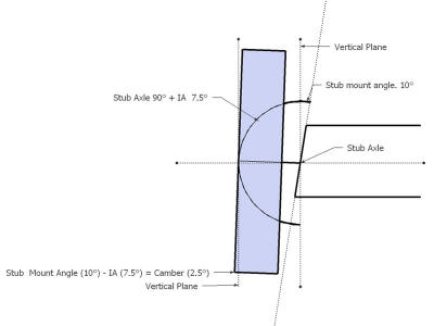
Replacing the Torana stub axle which has a included angle of 9 degrees with a A9X/HZ stub
axle
with a included angle of 7.5 degrees will increase negative camber by 1.5 degrees. Camber
is reduced by removing shims from between the k-frame and the UCA pivot arm. You
will need to remove approximately 0.25" of shims to compensate for the
difference in included angle between the Torana and A9X/HZ stub axles. Track cars typically run
significantly more camber than a street car so the increase is negative camber
is a bonus.
|
|
|
|
Torana Stub Axle (Included Angle 9°)
Arbituary stub mount angle of 10° for illustration.
|
|
|
|
HZ Stub Axle (Included Angle 7.5°)
Arbituary stub mount angle of 10° for illustration.
|
|
|
|
A9X bump stop spacer.
As the HZ stub axles lower the car around 30 mm the bump stops are raised on the A9X to reduce suspension travel. |
|
|
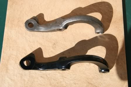
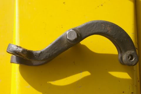
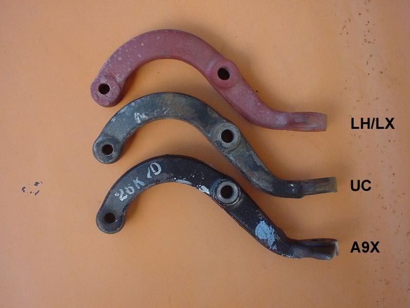
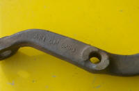
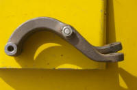
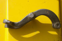
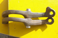
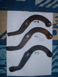
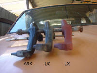
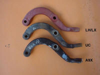
Steering Arms
The steering arms are
different for each model. The tie rod end of the arm gets progressively lower
and longer thoughout the LH/LX/UC/A9X. Reproduction A9X steering
arms are available from Harrop.
The UC has more
caster than the LX due to the offset ball joint in the UV UCA. When the caster
is increased, the tie rod end of steering arm is raised. The lower UC steering
arm corrects the changes to the steering rack geometry caused by the caster
increase.
|
LH |
Left |
9928327 |
|
|
Right |
9928326 |
|
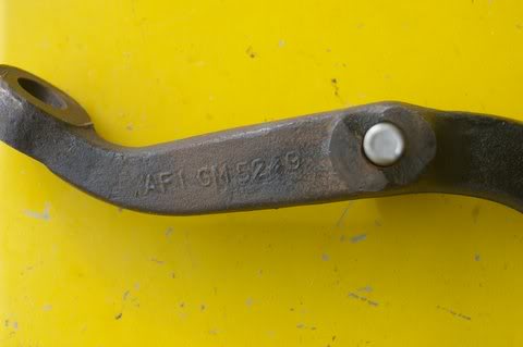
L34 |
Left |
9935249
(GM5249) |
|
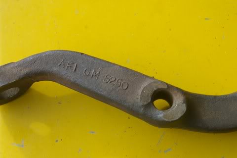
|
Right |
9935250
(GM5250) |
|
LX |
Left |
9928329
(GM8329) |
|
|
Right |
9928328
(GM8328) |
|
A9X |
Left |
92001894 |
|
|
Right |
92001893 |
|
UC |
Left |
9947249
(GM7249) |
|
|
Right |
9947248
(GM7248) |
|
|

|
|
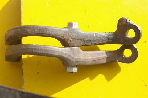
LX top, UC bottom.
Picture by hatchssv8
|
|

|
|
L34 Left 9935249
Picture by slr5640
|
|
|
|
L34 Right 9935250
Picture by slr5640
|
|
|
|
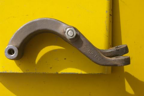
L34 infront of UC
Picture by slr5640
|
|
|
|
L34 at rear
Picture by slr5640
|
|
|
|
|
|
UC top, L34 bottom
Picture by slr5640
|
|
|
|
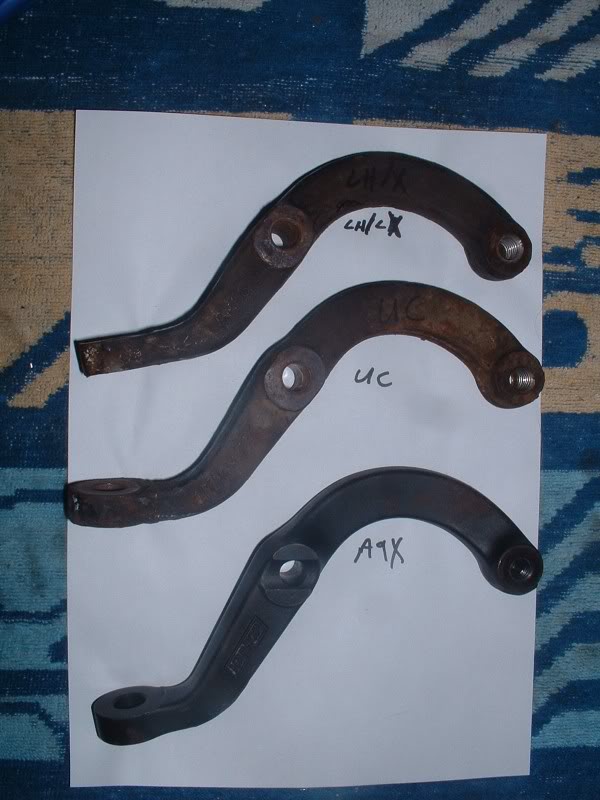
The arm labeled A9X is a Harrop reproduction.The Harrop arms do not have a steering stop. The A9X do have a steering stop.
Picture by ToranaMat69
|
|
|
|
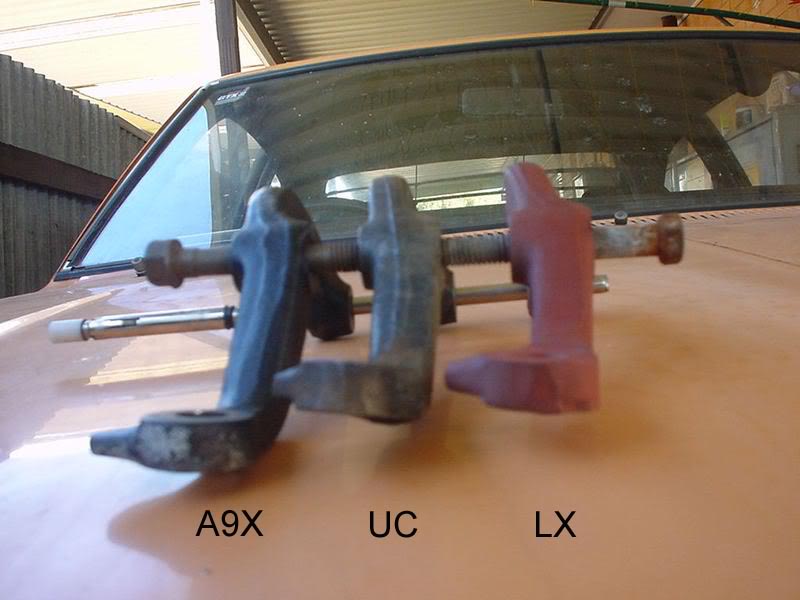
Note the A9X steering stop.
Picture by dangerous
|
|
|
|
Picture by dangerous
|
|
|
|
Picture by dangerous
|
|
|
Steering Racks
The LH and LX steering racks
are rubber mounted. The UC and A9X steering racks both solid mounted but use
different methods. The steering rack mount bolt locations are not changed.
Replacement rack end bushes (inner tie rod bushes) are available for the LX and UC racks but not for
the LH racks.
The
steering ratio is the number of degrees the steering wheel is turned to turn
the
road wheel 1°. An 18:1 steering ratio means that you turn the steering
wheel 18° to turn the road wheel 1°. The lower the ratio the faster and
heavier the steering. The steering ratio will change if the
length of the steering arms are changed. The LH, LX, UC and A9X all have
slightly different length steering arms and therefore would produce slightly
different steering ratios with the same rack.
According to ToranaMat69's measurements the Torana front wheel turns 65° from lock to lock, 34° in and
31° out. Using this figure we can calculate the following.
18:1 65 * 18.0 / 360 = 3.25 turns lock to lock.
20.4:1 65 * 20.4 / 360 = 3.68 turns lock to lock.
25:1 65 * 25.0 / 360 = 4.51 turns lock to lock
The
following are rack part numbers and the ratios.
9932244 18:1
(LH Right hand Drive. 3.25 turns lock to lock. Source LH Parts Manual pg
371) 3.68 turns lock to lock
9932245 18:1
(LH Left Hand Drive. 3.25 turns lock to lock. Source LH Parts Manual pg 371)
9942632 20.4:1
(LX Right Hand Drive. 3.68 turns lock to lock. Source LX Parts Manual pg
379)
9942633 20.4:1
(LX Left Hand Drive. 3.68 turns lock to lock. Source LX Parts Manual pg 379)
9940277 20.4:1
(UC Right Hand Drive. 3.68 turns lock to lock. Source UC Parts Manual pg
06-10)
92001807
(A9X Right hand Drive. ??
turns lock to lock.
Source LX Torana Performance Equipment
Package - Option A9X pg 5)
Steering Pinion
VS12501
(LH
Right Hand Drive. Source LH Parts Manual pg 375)
VS12502
(LH
Left Hand Drive. Source LH Parts Manual pg 375)
VS12501
(LX
Right Hand Drive. Source LH Parts Manual pg 384)
VS12502
(LX
Left Hand Drive. Source LH Parts Manual pg 384)
VS13851
(UC Right Hand Drive. Source UC Parts Manual pg 06-4)
Steering Rack
Part Number. Picture by A9X
 I have
collected the following rack travel measurements as another method of
identifying racks.
LH
rack travels 63 mm for 1.5 turns
UC
rack travels 55 mm for 1.5 turns
If the UC rack is 20.4:1, the rack travels 55 mm
for 1.5 turns and there are 3.68 turns from lock to lock then the total rack
travel is 135 mm.
Using
the above figures.
The LH rack travels 63 mm for 1.5 turns of the wheel.
This
would require 135 / ( 63 / 1.5 ) = 3.21 turns for lock to lock which gives a
ratio of 360 / ( 65 / 3.21 ) = 17.87 which is close enough to 18:1.
On
this basis the 25:1 rack would travel 135 / 4.51 * 1.5 = 45 mm for 1.5
turns.
I have
collected the following rack travel measurements as another method of
identifying racks.
LH
rack travels 63 mm for 1.5 turns
UC
rack travels 55 mm for 1.5 turns
If the UC rack is 20.4:1, the rack travels 55 mm
for 1.5 turns and there are 3.68 turns from lock to lock then the total rack
travel is 135 mm.
Using
the above figures.
The LH rack travels 63 mm for 1.5 turns of the wheel.
This
would require 135 / ( 63 / 1.5 ) = 3.21 turns for lock to lock which gives a
ratio of 360 / ( 65 / 3.21 ) = 17.87 which is close enough to 18:1.
On
this basis the 25:1 rack would travel 135 / 4.51 * 1.5 = 45 mm for 1.5
turns.
Wheel Alignment
The
following table contains wheel alignment setting from various sources. Some
wheel alignment shops will work in time instead of degrees. Using time one
degree is 60 minutes.
|
Degrees |
Time |
|
1.00 |
1:00 |
|
0.75 |
0:45 |
|
0.50 |
0:30 |
|
0.25 |
0:15 |
|
|
Castor |
Camber Left |
Camber
Right |
|
|
Description |
Degrees |
Time |
Degrees |
Time |
Degrees |
Time |
Toe |
|
Axistr LX |
+1.0 to
+1.5 |
+1:00 to
+1:30 |
+0.25 to
+0.33 |
-0:15 to
-0:20 |
0.00 to
+0.25 |
0:00 to
+0:15 |
0.00 mm |
|
Axistr Power Steering |
+2.5 to
+3.0 |
+2:30 to
+3:00 |
-0.25 to -0.33 |
-0:15 to
-0:20 |
0.00 to
+0.25 |
0:00 to
+0:15 |
0.00 mm |
|
UC/A9X |
+2.00 |
+2:00 |
-1.00 |
-1:00 |
-1.00 |
-1:00 |
+1.50 mm |
|
Gregorys
Manual LX |
-1.00 to -2.00 |
+1:00 to -2:00 |
+1.00 to 0.00 |
+1:00 to 0:00 |
+1.00 to 0.00 |
+1:00 to 0:00 |
+1.59 mm |
|
LH |
-1.00 +/- 1.00 |
-1:00 +/- 1:00 |
+0.25 +/- 0.75 |
+0:15 +/- 0:45 |
+0.25 +/- 0.75 |
+0:15 +/- 0:45 |
0 +/- 1/8” |
|
L34 |
-0.50 +/- 1.50 |
-0:30 +/- 1:30 |
-0.25 +/- 0.75 |
-0:15 +/- 0:45 |
-0.25 +/- 0.75 |
-0:15 +/- 0:45 |
0 +/- 1/8” |
|
A9X |
+1.00 +/- 0.50 |
+1:00 +/- 0:30 |
-1.00 +/- 0.50 |
-1:00 +/- 0:30 |
-1.00 +/- 0.50 |
-1:00 +/- 0:30 |
3/16" +/- 1/16" |
|
Gregorys
Manual UC |
+1.00 to +3.00 |
+1:00 to +3:00 |
-2.00 to 0.00 |
-2:00 to 0:00 |
-2.00 to 0.00 |
-2:00 to 0:00 |
0.00mm to +0.95 mm |
|
UC/A9X |
+2.00 +/- 0.30 |
+2:00 +/- 0:18 |
-1.00 +/- 0.30 |
-1:00 +/- 0:18 |
-1.00 +/- 0.30 |
-1:00 +/- 0:18 |
+1.50 mm |
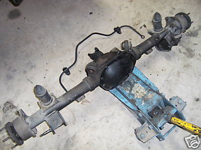
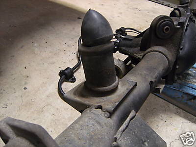
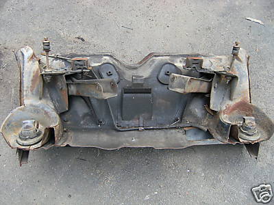
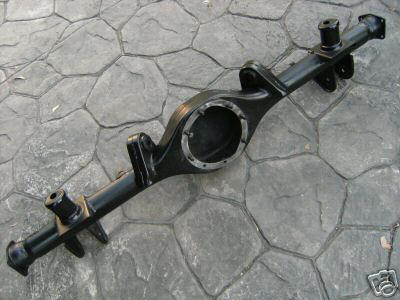
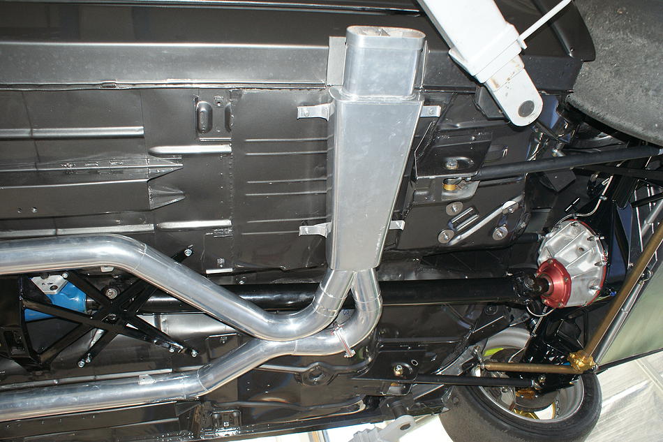
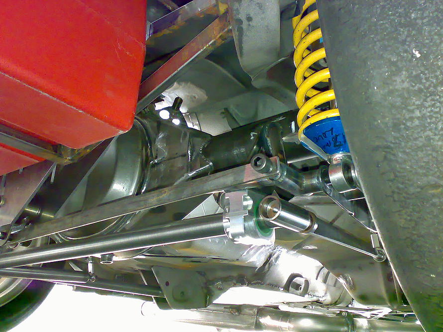
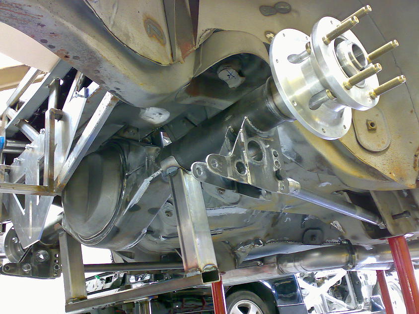
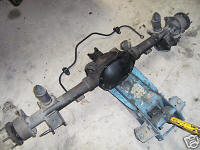
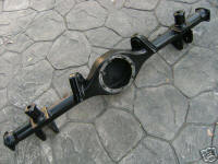
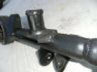
Differential
The A9X had
a Salisbury diff. The upper control arms on the Salisbury diff are on a
different angle to the LH and LX Torana diffs. To fit the Salisbury diff in
the A9X GMH produced a patch section for the floor pan to change the angle
of the upper control arm mounts and provide more room for the larger diff.
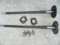
The A9X also had taller bump stops welded to the housing. The L34 had a
banjo diff which had extra baffles and the taller bump stops.
|
|
|
|
A9X Salisbury diff with taller bump stops
|
|
|
|
A9X Salisbury diff with taller bump stops
|
|
|
|
A9X floor patch to suit Salisbury diff.
|
|
|
|
L34 banjo housing with taller bump stops and baffles
|
|
|
|
L34 banjo housing with taller bump stops and baffles
|
|
|
|
|
|
L34 axles
|
|
|
Swaybar Options
Front Swaybar
1. Factory swaybar
2. Whiteline BHF37 24 mm
rear mount (factory style)
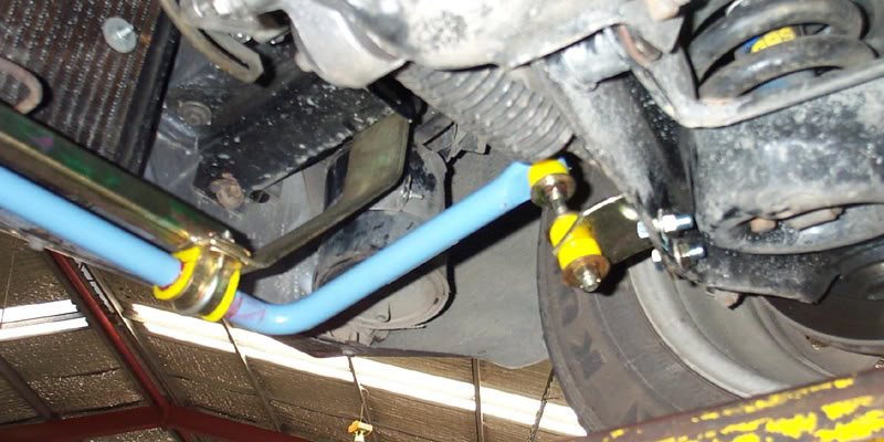
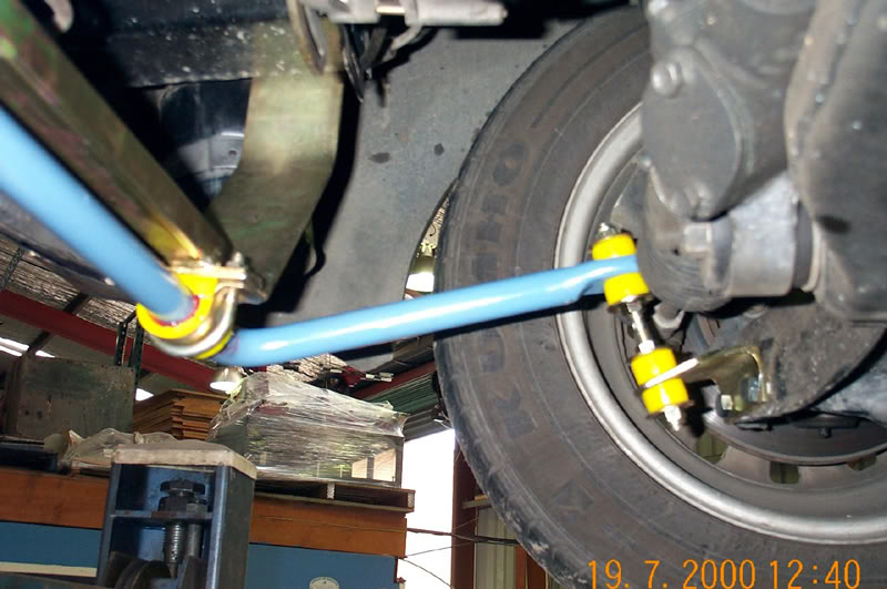
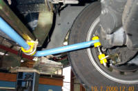
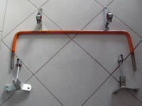
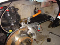
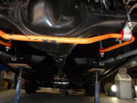
3. Whiteline BHF35 24 mm
front mount
4. K-MAC TFC4 24 mm front mount
adjustable (Bathurst design)
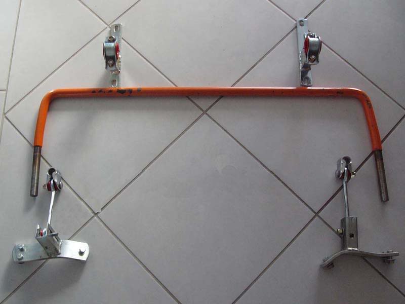
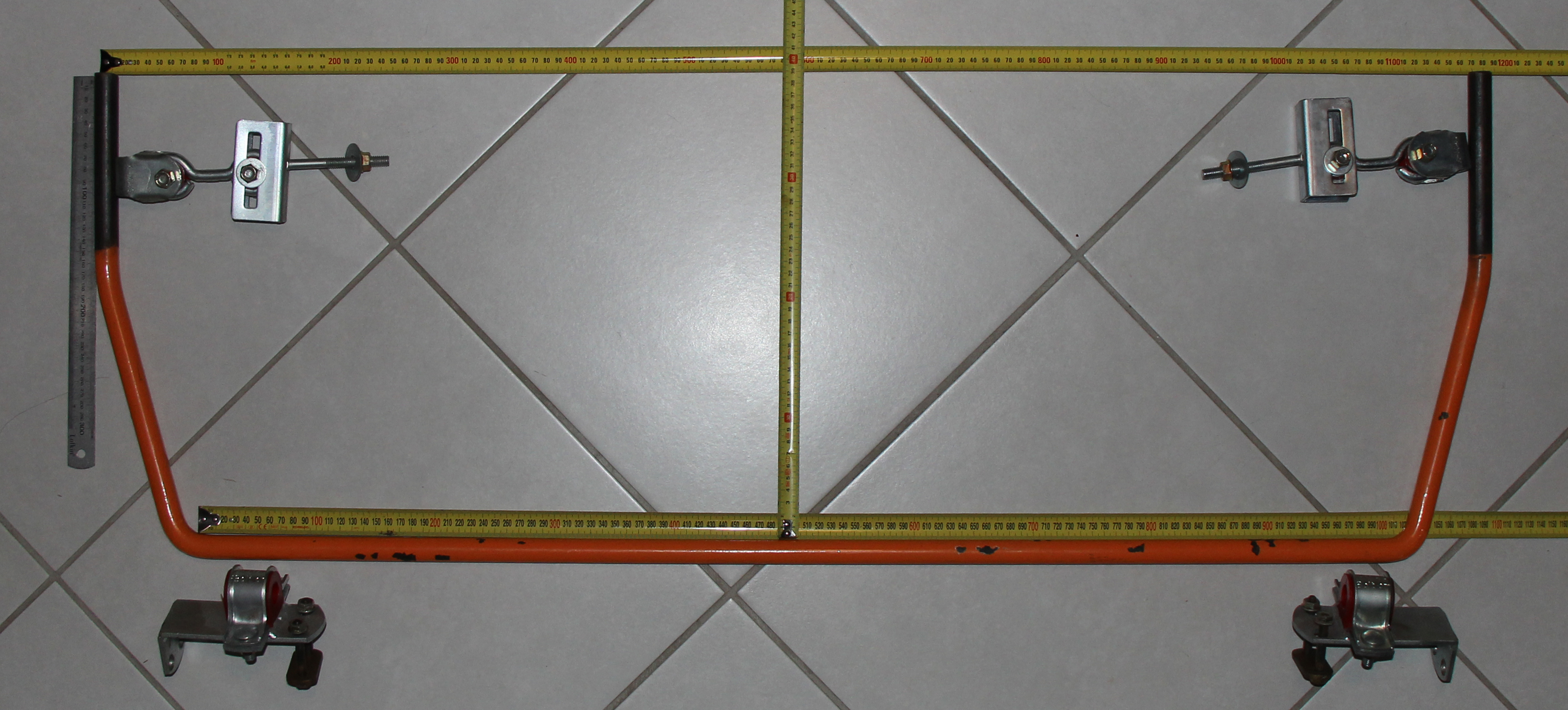
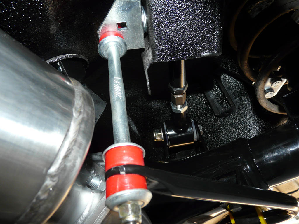
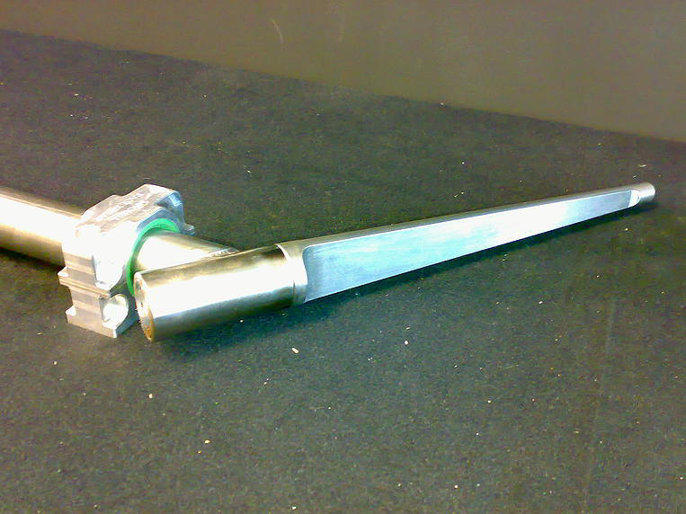
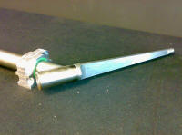
5. Custom made adjustable
knife blade.
www.mrx.co.nz
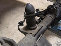
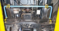
Rear Swaybar
1. Factory LH/LX trailing
arm mounted swaybar. This is the least effective of all swaybar designs.
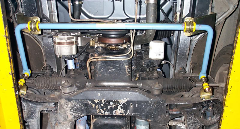
2. Factory UC front mounted
swaybar.
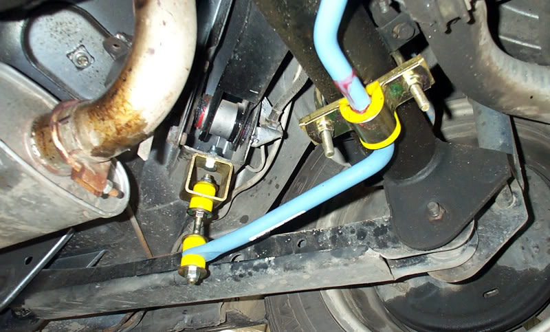
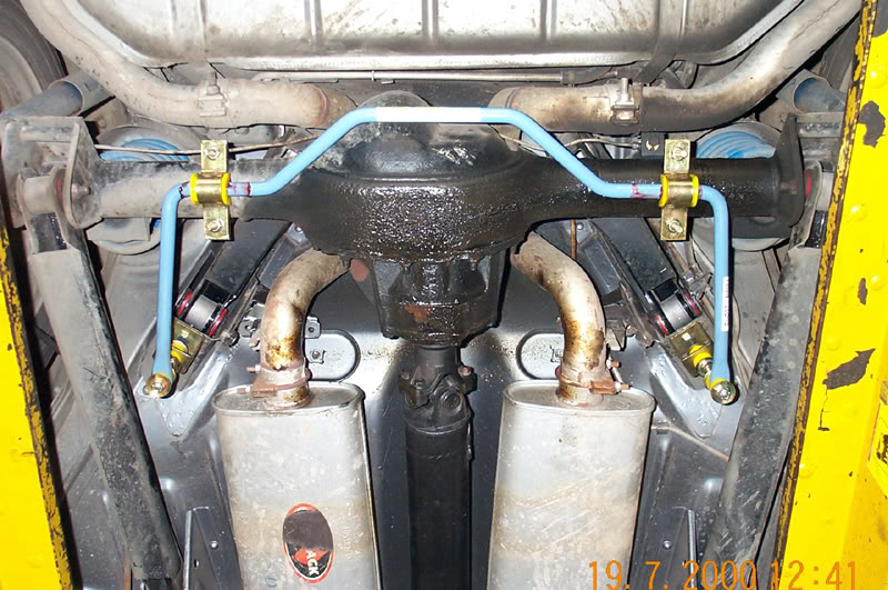
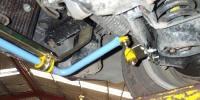
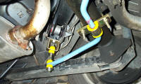
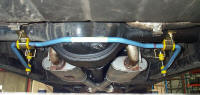
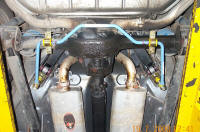
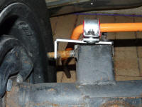
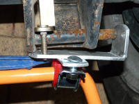
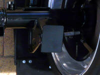
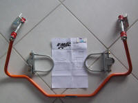
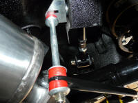
2. Whiteline BHR37 18 mm
front mount (similar to UC)
3. Whiteline BHR35 18 mm
trailing arm mount ( similar to LH/LX)
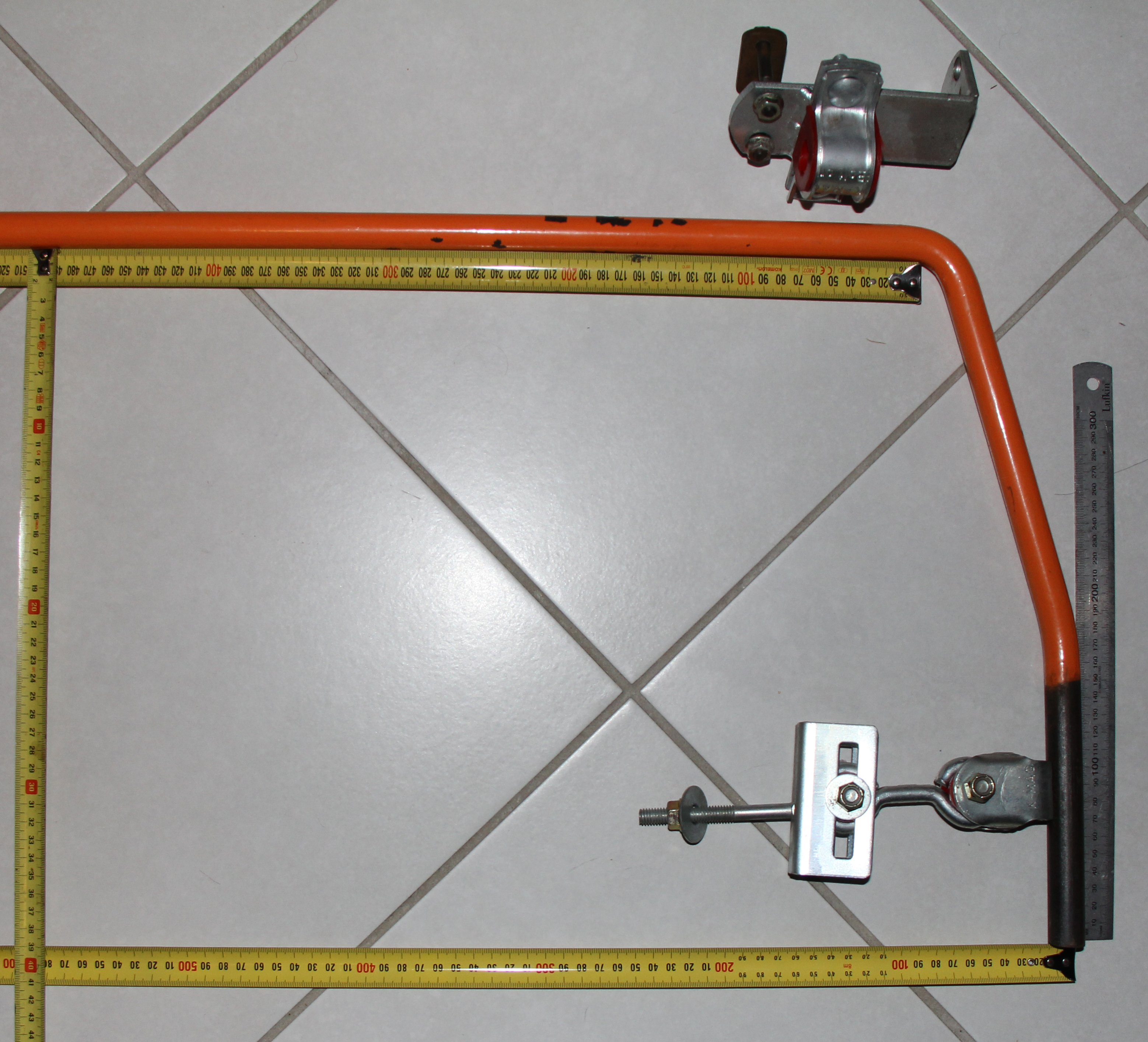
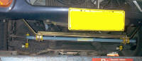
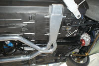
3. K-MAC TRC1 18/20 mm front mount (similar to UC)
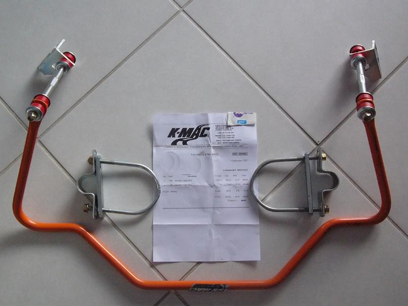
4. K-MAC TRC4 18/20 mm rear mount
adjustable (Bathurst design)
5. Custom made adjustable
knife blade.
www.mrx.co.nz
|
|
|
|
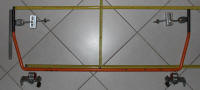
Whiteline BHF35 Front mount front swaybar
|
|
|
|
Whiteline BHF35 Front mount front swaybar
|
|
|
|
Whiteline BHF35 Front mount front swaybar
|
|
|
|
Whiteline BHF35 Front mount front swaybar
|
|
|
|
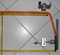
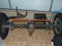
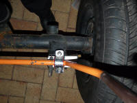
Whiteline BHR37 Front mount rear swaybar
|
|
|
|
|
|
Whiteline BHR37 Front mount rear swaybar
|
|
|
|
Whiteline BHR37 Front mount rear swaybar
|
|
|
|
K-MAC TFC4 Front mount adjustable front swaybar
|
|
|
|
K-MAC Front mount adjustable front swaybar. Picture by Rorym
|
|
|
|
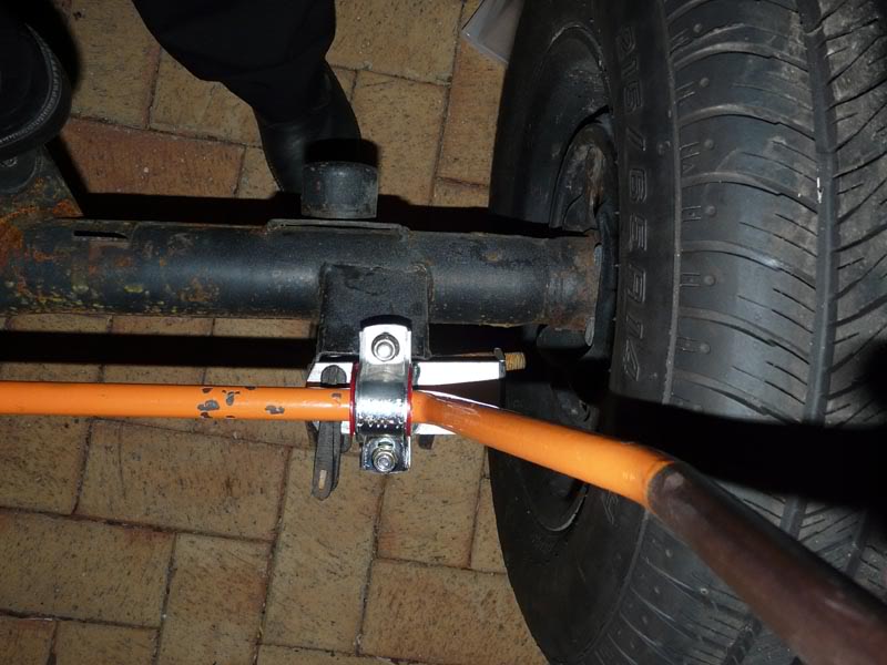
K-MAC TRC4 rear mount adjustable rear swaybar
|
|
|
|
|
|
K-MAC TRC4 rear mount adjustable rear swaybar
|
|
|
|
K-MAC TRC4 rear mount adjustable rear swaybar
|
|
|
|
K-MAC TRC4 rear mount adjustable rear swaybar
|
|
|
|
K-MAC TRC4 rear mount adjustable rear swaybar
|
|
|
|
K-MAC TRC4 rear mount adjustable rear swaybar
|
|
|
|
|
|
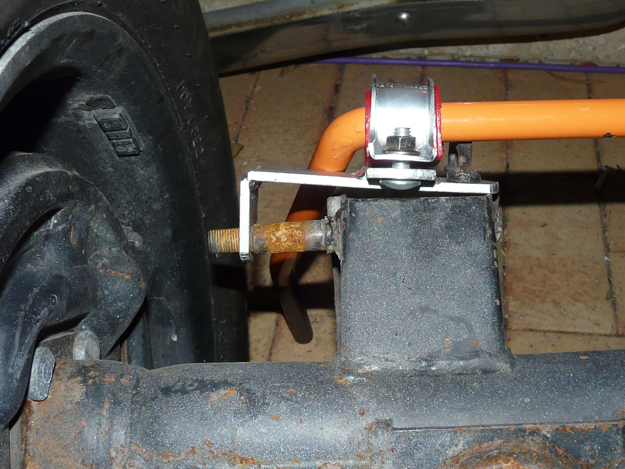
K-MAC TRC4 rear mount adjustable rear swaybar. Plate welded to mount swaybar instead of using brackets.
|
|
|
|
K-MAC TRC1 front mount rear swaybar. K-MAC forgot to supply the u-bolt bushes.
|
|
|
|
K-MAC TRC1 front mount rear swaybar
|
|
|
|
K-MAC TRC1 front mount rear swaybar
|
|
|
|
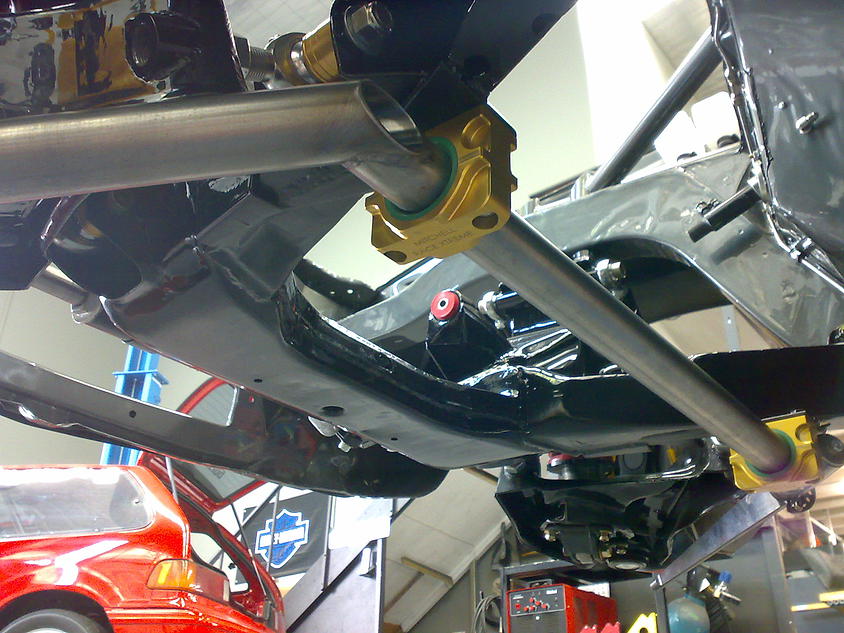
Knife blade adjustable swaybar. Can be made adjustable from under the car or in the cabin for race applications.
|
|
|
|

|
|
Knife blade front swaybar on Clark Hopkins Hatch
|
|

|
|
Knife blade front swaybar on Clark Hopkins Hatch
|
|
|
|
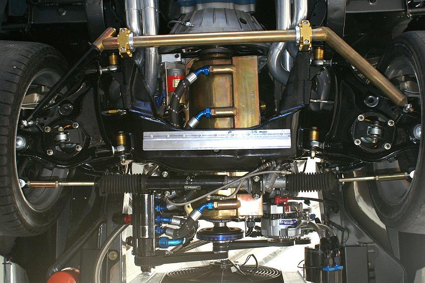
Knife blade rear swaybar on Clark Hopkins Hatch
|
|

|
|
Knife blade rear swaybar on Clark Hopkins Hatch
|
|

|
|
Knife blade rear swaybar on Clark Hopkins Hatch
|
|
|
[ Home ] [ Accessory Drive ] [ Bonnet Hinges ] [ Cooling ] [ Calculators ] [ Conversion Parts ] [ Drivetrain ] [ Electric Windows ] [ Engine ] [ Engine Install ] [ Engine Mounts ] [ Fuel Tank ] [ Interior ] [ Movies ] [ Oil Pans ] [ Power Steering ] [ Seat Rails ] [ Specifications and NCOP ] [ Starter Motors ] [ Suspension ] [ Wipers ] [ Links ]